Layer 3: Network Layer Routing and IP Addressing Guide
Layer 3 Is the Network Layer for Routing and IP Addressing
Layer 3 Is the part of the OSI model that moves packets between different networks. It handles logical addressing, routing decisions, packet forwarding, fragmentation, and traffic paths across routers. When people talk about IP addresses, subnets, default gateways, routing tables, ICMP messages, and IPv4 or IPv6 delivery, they are usually talking about Layer 3. It is the layer that lets devices communicate beyond a single local link.
Layer 3 sits between the data link layer and the transport layer. Layer 2 can move frames across a local network segment, while Layer 4 can manage end-to-end conversations with TCP or UDP. Layer 3 connects those worlds by giving packets a source address, a destination address, and a route that can cross many networks before the data reaches the final host.
What is Layer 3 in the OSI model?
Layer 3 is commonly called the network layer. Its job is to provide logical communication across multiple networks, not just across one cable, switch, Wi-Fi cell, or local broadcast domain. A laptop, server, router, firewall, cloud instance, or mobile device can use Layer 3 addressing to identify where traffic should go even when the destination is many hops away.
Layer 3 is most strongly associated with the Internet Protocol. IPv4 addresses such as 192.0.2.10 and IPv6 addresses such as 2001:db8::10 are Layer 3 identifiers. They are different from MAC addresses, which operate at Layer 2 and are used only on the local link. Layer 3 addresses are designed to be routed, summarized, filtered, translated, and planned across large environments.
Layer 3 also gives networks a way to divide address space into subnets. A subnet groups hosts that can usually reach one another directly through the same local network. When a host needs to reach a device outside its subnet, it sends traffic to a default gateway. That gateway is typically a router or firewall performing Layer 3 forwarding.
Layer 3 matters because modern networks are rarely flat. Homes have local networks, offices have VLANs, data centers have segmented application tiers, and cloud platforms have virtual networks. The internet itself is a massive set of routed networks. Layer 3 is the logic that makes those separate areas reachable without making every device part of one giant local segment.
How does Layer 3 routing work?
Layer 3 routing begins when a device creates an IP packet with a source address and destination address. The device compares the destination address with its own subnet rules. If the destination appears local, the device asks Layer 2 to deliver the frame directly. If the destination is remote, the device sends the packet to its configured gateway.
Layer 3 routers inspect the destination IP address and compare it with a routing table. A routing table is a set of known networks and next hops. The router chooses the best matching route, rewrites the local Layer 2 frame for the next segment, and forwards the same Layer 3 packet onward. The packet may cross many routers before it reaches the destination network.
Layer 3 forwarding is hop-by-hop. Each router only needs to know the next useful direction, not every physical detail of the entire route. That design allows huge networks to scale. A packet leaving a small office can pass through a firewall, an internet service provider, regional backbone routers, and a cloud edge before arriving at a web server.
Layer 3 route selection can be simple or complex. A home router may only have a local route and a default route toward the internet. A business router may use static routes, OSPF, BGP, policy-based routing, or dynamic failover. In each case, Layer 3 depends on accurate addressing, reachable next hops, and routing information that reflects the current network.
Why are IP addresses and subnets central to Layer 3?
Layer 3 cannot route well without a structured addressing plan. IPv4 and IPv6 addresses identify interfaces, but subnets define which addresses belong together. A subnet mask or prefix length, such as /24 in IPv4 or /64 in IPv6, tells a device which portion of the address represents the network and which portion identifies the host.
Layer 3 subnetting helps administrators control traffic flow. For example, workstations may live in one subnet, servers in another, voice devices in another, and guest Wi-Fi in a separate network. That separation makes routing, firewall rules, monitoring, and troubleshooting easier. It also reduces unnecessary broadcast exposure because Layer 3 boundaries stop Layer 2 broadcasts from spreading everywhere.
Layer 3 planning should be boring in the best possible way. Address ranges should be documented, summarized where possible, and chosen to avoid overlaps. Overlapping private networks can create serious problems with VPNs, cloud connections, mergers, and remote access. A clean Layer 3 address plan makes future routing changes less fragile.
Layer 3 also includes important support protocols. ICMP helps report errors and test reachability with tools such as ping and traceroute. ARP and neighbor discovery connect Layer 3 addressing to local Layer 2 delivery. DHCP can assign IP configuration automatically, although DHCP itself is often discussed alongside several layers because it supports practical network setup.
What does Layer 3 do for packet forwarding?
Layer 3 packet forwarding is the process of moving a packet toward its destination based on the destination IP address. A router receives a frame, removes the local Layer 2 wrapper, examines the Layer 3 header, decrements the time-to-live or hop-limit value, and chooses an outgoing interface. It then places the packet into a new Layer 2 frame for the next link.
Layer 3 does not guarantee that an application session will succeed. That responsibility is shared with upper layers and the application itself. The network layer focuses on delivery across networks, while TCP can handle retransmission and ordering at Layer 4. This division keeps Layer 3 efficient and lets routers forward traffic without tracking every application detail.
Layer 3 can also fragment packets in some IPv4 situations when a packet is too large for a link. In IPv6, fragmentation is handled differently and is generally expected from the source host rather than intermediate routers. Either way, packet size matters. MTU mismatches can cause slow connections, broken VPN traffic, or strange failures where small requests work but larger transfers fail.
Layer 3 forwarding becomes more powerful when combined with quality of service markings, access control lists, and traffic engineering. Networks may prioritize voice, video, business applications, or control traffic. Those choices should be made carefully because poor QoS design can hide capacity problems or unfairly starve less obvious but important services.
Where is Layer 3 used in real networks?
Layer 3 appears anywhere traffic crosses a network boundary. Home routers use Layer 3 to connect a private LAN to an internet provider. Enterprise firewalls use Layer 3 interfaces to route between security zones. Data center fabrics use Layer 3 routing to connect server networks. Cloud platforms use Layer 3 constructs such as route tables, virtual private networks, subnets, gateways, and peering.
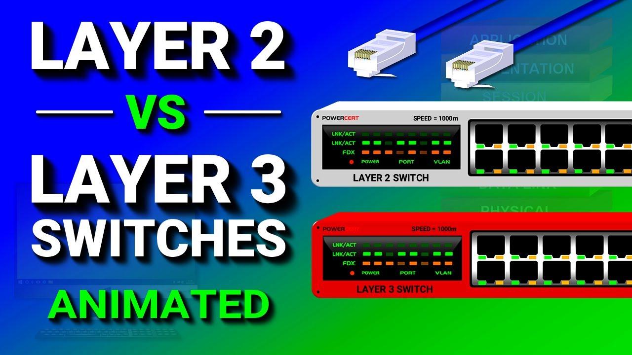
Layer 3 switches are common in campus networks. They combine high-speed switching hardware with routing features, allowing VLANs to communicate without sending every packet to a separate router. A Layer 3 switch can act as the gateway for many VLANs, apply routing policies, and move traffic efficiently inside an office, school, warehouse, or hospital network.
Layer 3 is also essential for VPNs. Site-to-site VPNs connect private networks across the internet, and remote access VPNs place a user into a routed network path. In both cases, the design depends on IP ranges, routes, encryption boundaries, and firewall policies. A VPN can be secure in principle while still failing in practice if Layer 3 routes are missing or overlapping.
Layer 3 supports troubleshooting workflows that network teams use every day. When a service is unreachable, engineers often check the local IP address, subnet mask, default gateway, DNS behavior, routing table, firewall path, and traceroute output. Those steps reveal whether the problem is local configuration, path selection, filtering, name resolution, or something higher in the stack.
If you are comparing adjacent layers, it helps to study and alongside this topic. Layer 3 is easier to understand when you can see what it receives from the local link and what it hands upward to TCP, UDP, and application protocols.
How do you set up Layer 3 connectivity step by step?
Layer 3 setup starts with knowing the networks that need to communicate. A small setup may involve one LAN, one router, and one internet connection. A larger setup may involve many VLANs, firewall zones, cloud subnets, VPN tunnels, and dynamic routing peers. The principle is the same: every source needs a valid address, every destination needs a known path, and return traffic needs a path back.
Layer 3 configuration should be tested in stages. Confirm that the local interface has the right IP address and prefix. Confirm that the gateway is reachable. Confirm that routing tables include the destination network. Confirm that security policies allow the traffic. Then test by IP address before testing by DNS name, application URL, or user-facing service.
Layer 3 implementation usually follows a practical workflow:
Define the required networks, subnets, gateways, and address ranges.
Assign IP addresses to router, firewall, switch, server, and client interfaces.
Create static routes or enable a routing protocol where dynamic updates are needed.
Apply firewall and access policies that match the intended traffic path.
Test reachability, packet size, failover behavior, and return routing.
Layer 3 changes should be documented before and after deployment. Even a small subnet change can affect DHCP scopes, firewall objects, NAT rules, monitoring systems, VPN definitions, DNS records, and cloud security groups. Good documentation is not busywork; it is what lets the next person understand why the network behaves the way it does.
What are the benefits of Layer 3 segmentation?
Layer 3 segmentation gives a network clear boundaries. Instead of placing every device in one broad local environment, teams can route between smaller networks with explicit policies. This makes traffic easier to inspect, restrict, and prioritize. It also reduces the chance that a noisy or misconfigured device disrupts unrelated parts of the environment.
Layer 3 routing can improve scalability. Large Layer 2 networks can become difficult to manage because broadcasts, loops, and spanning-tree behavior may create operational risk. Layer 3 boundaries limit the scope of those issues. Routed designs also allow better summarization, cleaner redundancy, and more predictable failover when planned properly.
Layer 3 can support security goals, but it is not security by itself. A subnet boundary only helps when paired with meaningful firewall rules, identity controls, logging, patching, and monitoring. Placing systems in separate networks without policy enforcement may improve organization, but it does not automatically stop unwanted access.
Layer 3 also gives teams more control over performance. Routing choices can send traffic over preferred links, isolate backup traffic, steer branch offices through secure paths, or keep internal traffic away from the public internet. These benefits depend on careful design, because a bad route can send packets through a slower, more expensive, or less reliable path.
What risks and mistakes should you watch for with Layer 3?
Layer 3 mistakes often look simple after they are found but confusing while they are happening. A wrong subnet mask can make a host think a remote address is local. A missing default gateway can keep a device trapped inside one subnet. A bad route can send packets into a dead end. A missing return route can make one-way traffic appear to vanish.
Layer 3 security mistakes are also common. Overly broad firewall rules may expose management interfaces, databases, or internal applications. Misconfigured NAT can make logs hard to interpret. Unplanned routing between guest, user, and server networks can weaken segmentation. Internet-facing Layer 3 services should be minimized, monitored, and verified against current vendor and platform documentation.
Layer 3 troubleshooting should avoid assumptions. If a route exists, confirm the next hop responds. If ping fails, check whether ICMP is blocked before concluding the host is down. If traceroute stops, remember that some routers suppress replies. If DNS works inconsistently, test raw IP connectivity separately. Layer 3 evidence is strongest when several checks point to the same cause.
Layer 3 designs also need change control. Adding a VPN, cloud peering link, or new private address range can accidentally overlap with an existing network. Route leaks can send traffic to the wrong place. Dynamic routing protocols can spread a mistake quickly. For production environments, verify details with official vendor documentation and use staged rollout procedures where possible.
How is Layer 3 different from Layer 2 and Layer 4?
Layer 3 is easiest to understand when compared with its neighbors. Layer 2 moves frames on the local network using MAC addresses. Layer 3 moves packets between networks using IP addresses. Layer 4 manages transport conversations using ports, sequence behavior, flow control, and protocols such as TCP and UDP.
Layer 3 does not replace Layer 2. Every routed packet still has to cross local links, and each local hop needs a Layer 2 frame. The difference is that the Layer 2 addressing changes at every hop, while the Layer 3 source and destination IP addresses usually remain focused on the original sender and final receiver.
Layer 3 also differs from Layer 4 because routers generally do not need to understand the full application session. A firewall or load balancer may inspect Layer 4 ports or even higher-layer data, but routing itself is primarily based on Layer 3 information. This separation lets the internet route many types of traffic without needing to know each application protocol in detail.
Layer
Main focus
Common examples
Layer 2
Local link delivery
Ethernet, Wi-Fi, MAC addresses, VLANs
Layer 3
Routing between networks
IPv4, IPv6, ICMP, routers, subnets
Layer 4
End-to-end transport
TCP, UDP, ports, sessions
When should you choose Layer 3 routing instead of another approach?
Layer 3 routing is the right approach when traffic must move between different IP networks, when segmentation matters, or when a design needs scale beyond a single broadcast domain. It is also the natural choice for connecting sites, cloud networks, user VLANs, server networks, and internet paths. Most serious network designs use Layer 3 heavily because it gives structure to growth.
Layer 3 may not be the only tool involved. Bridging, switching, tunneling, proxying, load balancing, and application gateways all have their place. A wireless network might rely on Layer 2 roaming inside a building, while routed Layer 3 boundaries separate departments or security zones. A web application might sit behind a Layer 7 proxy, but the packets still need Layer 3 paths to get there.
Layer 3 is not a magic fix for every network problem. If the issue is a bad cable, radio interference, duplex mismatch, or local switching loop, Layer 2 needs attention. If the issue is a blocked TCP port, overloaded application, TLS failure, or broken login flow, higher layers may be involved. Effective troubleshooting follows the path of the packet instead of blaming one layer too quickly.
Layer 3 remains one of the most important concepts in networking because it explains how separate networks become one reachable system. A good Layer 3 design gives every packet a logical address, a path, a return path, and a set of rules for crossing boundaries. Whether you are configuring a home router, a corporate WAN, a lab, or a cloud environment, Layer 3 is the foundation for reliable routed communication.
Reader rating:
4.5 / 5
based on 621 ratings
Questions and Answers
What does Layer 3 mean in networking?
Layer 3 means the network layer of the OSI model. It is responsible for logical addressing and routing packets between different networks. IP addresses, subnets, routers, default gateways, routing tables, and ICMP diagnostics are all closely tied to Layer 3. It lets a device communicate beyond its local network segment.
Is Layer 3 the same as IP routing?
Layer 3 is broader than IP routing, but IP routing is its most common real-world function. The layer includes logical addressing, route selection, packet forwarding, fragmentation behavior, and some diagnostic messaging. In modern TCP/IP networks, IPv4 and IPv6 are the main protocols people mean when they discuss Layer 3 routing.
How is Layer 3 different from Layer 2?
Layer 2 handles local delivery on the same network link using frames and MAC addresses. Layer 3 handles delivery between networks using packets and IP addresses. A switch usually works at Layer 2, while a router works at Layer 3. Many enterprise switches can do both, especially when routing between VLANs.
Why does Layer 3 need a default gateway?
A default gateway gives a host a place to send traffic when the destination is outside the local subnet. Without a gateway, the host may still communicate with nearby devices on the same subnet, but it cannot reliably reach remote networks. The gateway then uses Layer 3 routing rules to forward packets onward.
What are common Layer 3 troubleshooting steps?
Common Layer 3 checks include confirming the IP address, subnet mask or prefix length, default gateway, routing table, and firewall path. Tools such as ping, traceroute, route inspection, and packet capture can help show where traffic stops. It is also useful to test by IP address before testing DNS names or application URLs.
Can Layer 3 improve network security?
Layer 3 can support security by separating networks into routed segments, but segmentation alone is not enough. The design should also include firewall rules, access controls, logging, monitoring, and careful route management. A subnet boundary without enforcement may organize traffic, but it does not automatically prevent unauthorized access.
When should a network use Layer 3 switching?
Layer 3 switching is useful when a network needs fast routing between VLANs or internal subnets. It is common in campus and enterprise networks where many local segments must communicate efficiently. A Layer 3 switch can act as the gateway for multiple VLANs while still forwarding traffic at high speed.
The network layer (also packet level) provides a defined benefit services for switching connections and packet-oriented services for the relaying of data packets. The data transmission in both cases will go over the entire communication network and includes the route search (routing) between the network nodes. Because not always a direct communication between the sender and the target is possible, packets must be forwarded by nodes that are on the way. Next mediated packets do not reach the higher layers, but are provided with a new intermediate target and sent to the next node.
The main tasks of the network layer is one of providing cross-network addresses, the routing and the construction and updating of routing tables and the fragmentation of data packets. But the negotiation and ensure a certain quality of service falls within the remit of the network layer.
OSI Layer 3 - Network Layer
In the seven-layer OSI model of computer networking, the network layer is layer 3. The network layer is responsible for packet forwarding including routing through intermediate routers, since it knows the address of neighboring network nodes, and it also manages quality of service (QoS), and recognizes and forwards local host domain messages to the Transport layer (layer 4). The data link layer (layer 2) is responsible for media access control, flow control and error checking.
The network layer provides the functional and procedural means of transferring variable-length data sequences from a source to a destination host via one or more networks, while maintaining the quality of service functions.